Create a new schematic view and use library analogLib tsmc25rf to draw the scheme. Using Cadence Virtuoso and SpectreRF the complimentary.
2
The design investigated is the Hartley oscillator shown below.

. The design investigated is the Hartley oscillator shown below. Then call the window Affirma Analog Circuit Design Environment. Set Sweep Type linear.
OscHartley The VCO measurements described in this workshop are calculated using SpectreRF in the Analog Design Environment. I would suggest including a maximum integration time step of perhaps 1 or 2 ps maxstep 1 ps for example. VCO Design Using SpectreRF.
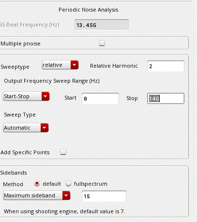
Ad Phase Locked Oscillators - Voltage Controlled Owcillators - Noise Sources More. Enable the Sweep button. The procedures described in this workshop are deliberately broad and generic.
If the VCO frequency is off the beat frequency by too much over sweeping Vctrl PSS may fail. The final VCO design meets all specifications. PDF VCO Design Using SpectreRF.
PLL-based frequency synthesizer using a simulation method that is both accurate and efficient. For component selection A-Mode varactor is a good device for variable capacitor the inductor and active devices are dependent on what frequency your VCO is working on. The oscillation frequency Fo is determined by the resonant circuit made up of inductors L0.
The VCO designs considered. VCO Specifications The VCO must exhibit a low Phase Noise in order to meet the Sensitivity Adjacent Channel and Blocking requirements. An eye fixed-catching style has never been simpler.
Mi-Wave provides a wide variety of Oscillators Sources PLOs Synthesizers for your needs. The design investigated is the Hartley oscillator shown below. However the period of your oscillator is 74 ps.
Do tran analysis first to estimate the VCO frequency at the fixed Vctrl as the Beat frequency. VCO Design Using SpectreRF Application Note. EECE 457 VCO Design Project Jason Khuu Erik Wu AbstractThis paper details the design and simulation of a Voltage Controlled Oscillator using a 013 mprocess.
Enter theta as VariableName. Push Variables Copy From Cellview and the defined variables appear in the Design Variables section. Null Copyright 2018 DOCSFORD Inc.
The oscHartley VCO uses the basic Hartley topology and is tunable between 720 MHz and 11 GHz. In cadence ic design tool there is a sample for how to simulate differential LC VCO it is under dfIIsampls directory. Use PAC to find how an interesting input frequency is modulated and attenuated to resulting frequencies at the output.
OscHartley The VCO measurements described in this workshop are calculated using SpectreRF in the Analog Design Environment. VCO Design Using SpectreRF. And Reference node gnd.
In cadence ic design tool there is a sample for how to simulate differential LC VCO it is under dfIIsampls directory. You can read the Spectre RF user guide for more help. For each block the phase noise is extracted.
The oscHartley VCO uses the basic Hartley topology and is tunable between 720 MHz and 11 GHz. Vco design using spectrerf To apply only stick on your nails we like to help keep them at The bottom of our nail beds and set with obvious topcoat. The design investigated is the Hartley oscillator shown below.
A Differential LNA The LNA measurements described in this workshop are calculated using SpectreRF in ADE. The methodology first partitions the PLL design into a few basic building blocks then uses transistor-level RF noise simulation to characterize the phase noise behavior of the blocks that make up the PLL. AndNumber of Steps 10Run the SimulationRun the swept PSS analysisDisplayData AnalysisClick Results--Direct Plot--Main.
The VCO measurements described in this workshop are calculated using SpectreRF in the Analog Design Environment. Your specific design might require procedures that are slightly different from the ones described in this application note. Hence the maximum time step is far too large and may result in simulator accuracy errors.
Dds 相位噪声 相位噪声 抖动 相位噪音. Make sure the VCO works by setting the Initial Condition tstab should be longer than the time the VCO needs to stable. Make sure the VCO works by setting the Initial Condition tstab should be longer than the time the VCO needs to stable.
Set the Sweep Range Start 0 and Stop 359. The oscHartley VCO uses the basic Hartley topology and is tunable between 720 MHz and 11 GHz. VCO Design Using SpectreRFVoltage Controlled Oscillator Design MeasurementsVout.
Vco Design Using Spectrerf. 文档格式pdf 文档页数 62页 文档大小 246M 文档热度. The VCO measurements described in this workshop are calculated using SpectreRF in the Analog Design Environment.
The oscHartley VCO uses the basic Hartley topology and is tunable between 720 MHz and 11 GHz. In your example this is 3048 ns50 609 ps. Request PDF VCO Design and Simulation Using TSMC 018 mm Process to Meet IEEE80211a Requirements A complimentary topology is used incorporating TSMC 018 mm process to design a CMOS VCO with.
The design investigated is the Hartley oscillator shown below. Setup up the Model Libraries. LNA Design Using SpectreRF _____ September 2011 Product Version 111 4 The Design Example.
All the VCO schematics presented below were practical build using the Infineon SiGe transistor BFP420 and any of them can be re-tuned for different frequency ranges changing varicaps and LC tank values. The design investigated is the differential low noise amplifier shown below. VCO Design Using SpectreRF Application.
Pss Simulation For Vco Rf Design Cadence Technology Forums Cadence Community
2
Vco Design Using Spectrerf Application Note

Cadence Vco Design Using Spectrerf A Marketplace Of Ideas
Spectrerf Workshop Vco Manualzz

Cadence Vco Design Using Spectrerf A Marketplace Of Ideas
2

Cadence Lna Pdf Amplifier Distortion
0 comments
Post a Comment